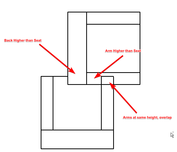
Sometimes… sometimes we just can’t help ourselves and we HAVE to draw 2D elements for reasons. Just reasons. When that happens you still want to care about graphical information and drawings looking correct. Having a Chair look like it’s in the same plane as a table just… well that ain’t right.
So this video is intended to give you a head start in the struggle against Masking Regions in 3D elements. More explanation after the video.
Here’s the thing about Masking Regions. They are still model elements. They use the real world dimension system that defines model elements as model elements in Revit (versus paper space dimensions of annotative elements in Revit). Their visibility graphics are driven from subcategories in the model tag in the Visibility Graphics and Object Styles dialog boxes. However, they are 2D elements. They are drawn on the Detail plane of the view which they are drawn on.

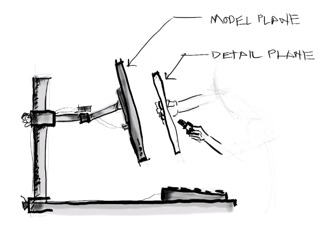
When you draw a detail line or masking region in a project, you draw it on a work plane that sits closer to your eye than the modeled elements being displayed in the view. Think of it as drawing on a piece of glass that you’re holding in front of the screen. So when you’re creating detail elements in a project view, they will always be on top of the modeled elements. However, if you go to a different view, they are all gone. That glass doesn’t exist in that view until you draw on it. Each view has its own glass.
This is a little bit different when you start drawing detail elements in a 3D family. For the sake of this discussion, let’s take everything in context to a height above floor level, a z-offset if you will. When we create detail elements in a 3D family, the default workplane is going to be the 3d point in the family furthest from the reference level plane.
POP QUIZ! If there's no 3D data in the family, which workplane will you be creating Masking Regions on in your family in a level view? Put your answer in the comments below!

Which means when we place Masking Regions in a blank 3D family, and then place the family in a project, you end up with overlapping Masking Regions. With no way to manage the draw order of detail elements nested in a family, we need to be able to help Revit figure out where we want the masking regions to appear to be. This is where workplanes come in.

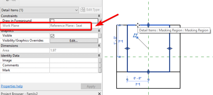
By drawing some reference planes and assigning the masking regions to those reference planes, we can control the z-offset of each individual masking region and give Revit the much needed instructions it needs to show the graphics properly.


Finally, we need to tell Revit to NOT draw this on the detail plane. Remember that piece of glass you were drawing on before? We want to draw on the workplane instead! The final piece to this puzzle is to uncheck the “Draw in Foreground” parameter in the options for the Masking Regions. Be sure you do this for each Masking Region you want to be placed on the workplane you’ve referenced.
That’s it! You should now have properly behaving 2D Graphics in a 3D family. Hope this helps, and I look forward to coming up with another tip. If you have any suggestions on what you’d like to see. Feel free to post in the comments below!

Till then,
-Carl
Sample File can be downloaded from here. (Sorry, Revit 2019)

2 responses to “Revit TotD – 7.3.2018 | Masking Regions in 3D Families”
Thanks carl!
Glad it was helpful! Thanks for stopping by!